


Introduction to the OSI Model
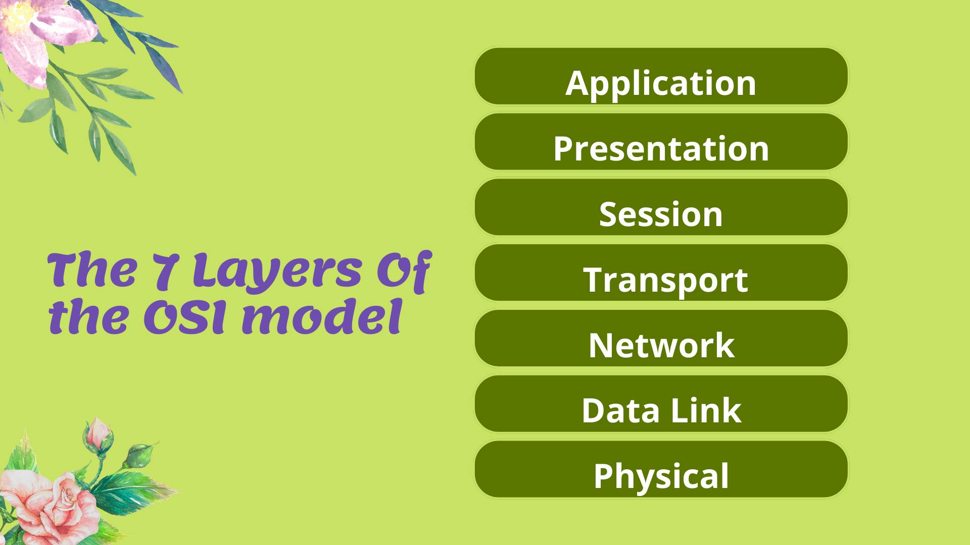
The OSI Model (Open Systems Interconnection Model) is a framework used to describe the functions of a networking system. The OSI model characterizes computing functions into a universal set of rules and requirements to support interoperability between different products and software. In the OSI reference model, the communications between a computing system are split into seven different abstraction layers:
Physical, Data Link, Network, Transport, Session, Presentation, and Application.
Physical
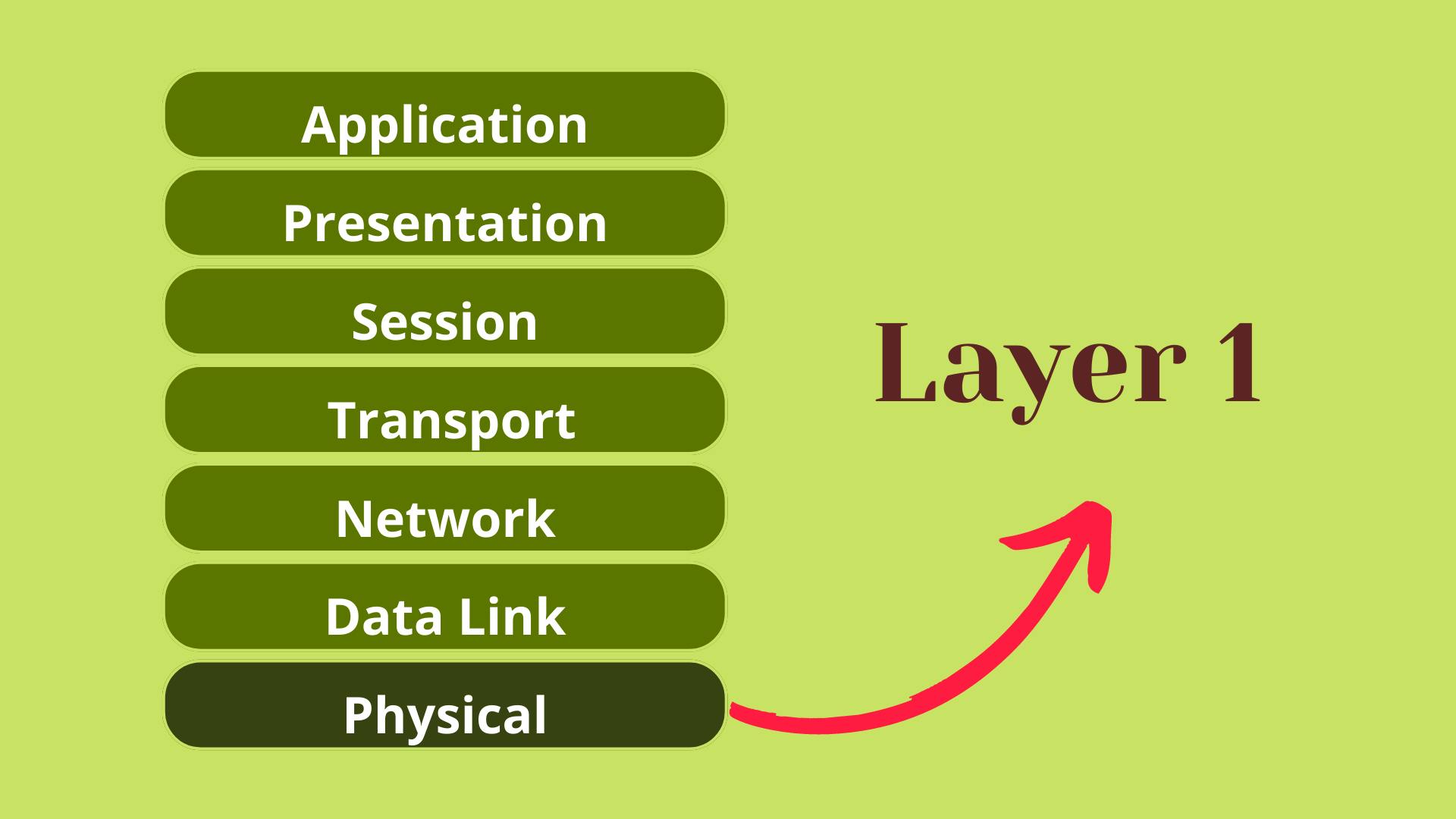
Layer 1 in the OSI model is known as physical, the premise of getting data from one host to another through a means be it physical cable or we could also consider Wi-Fi in this layer. We might also see more legacy hardware around hubs and repeaters to transport the data from one host to another.
- Cables:- Ethernet OR Fibre OR Wifi OR Hubs
- Transporting Bits:- Data Exists in the form of Bits (1's & 0's). Something needs to transport those Bits Between hosts.
Data Link
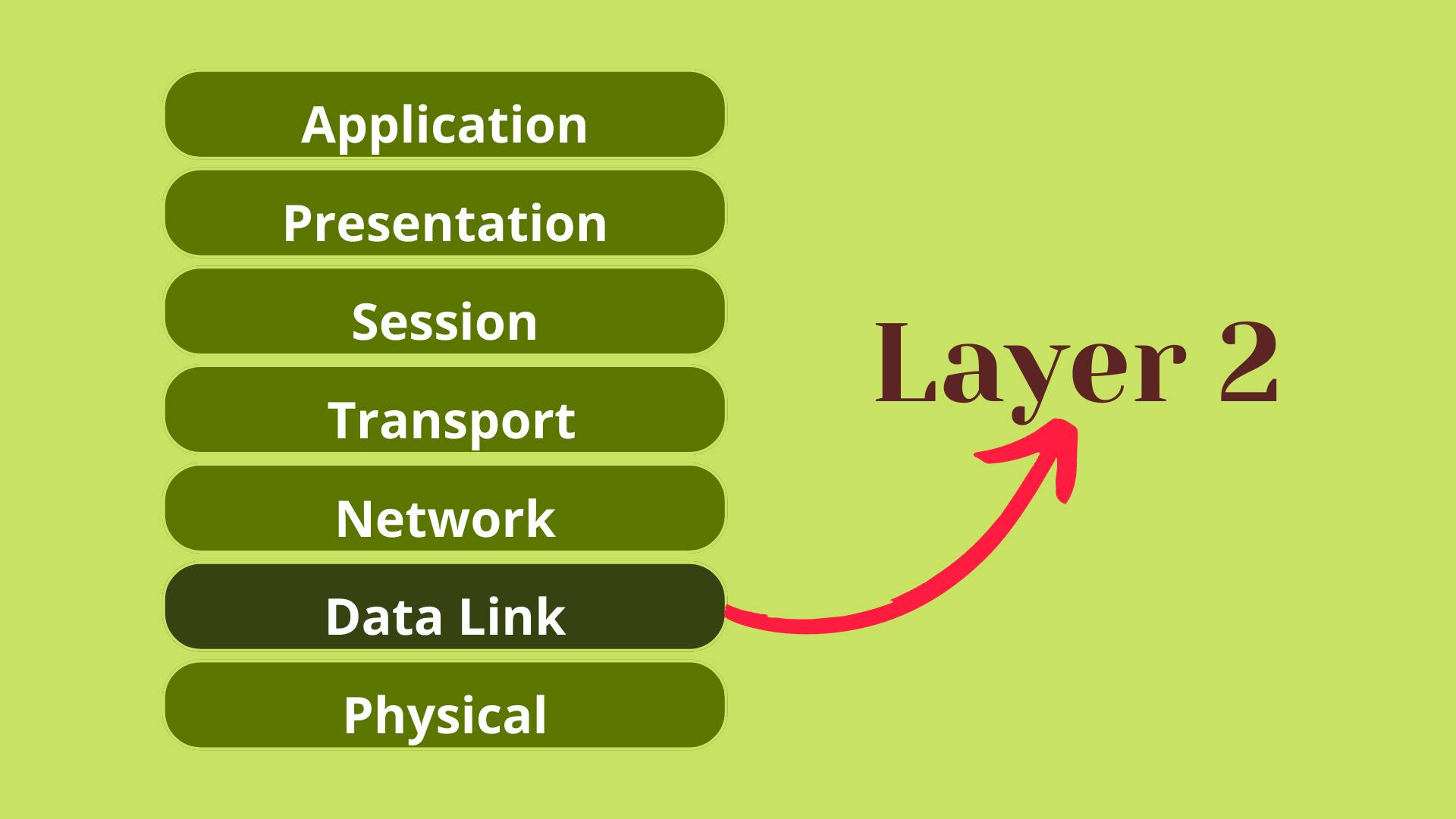
Layer 2, the data link enables a node-to-node transfer where data is packaged into frames. There is also a level of error-correcting that might have occurred at the physical layer. This is also where we introduce or first see MAC addresses. Every networking device has its own MAC address which can't be changed. When you connect your Router with the switch it stores the mac address.
Interacts with the cable:- Network interface card, wifi access cards, switches
Addressing Scheme MAC
Network
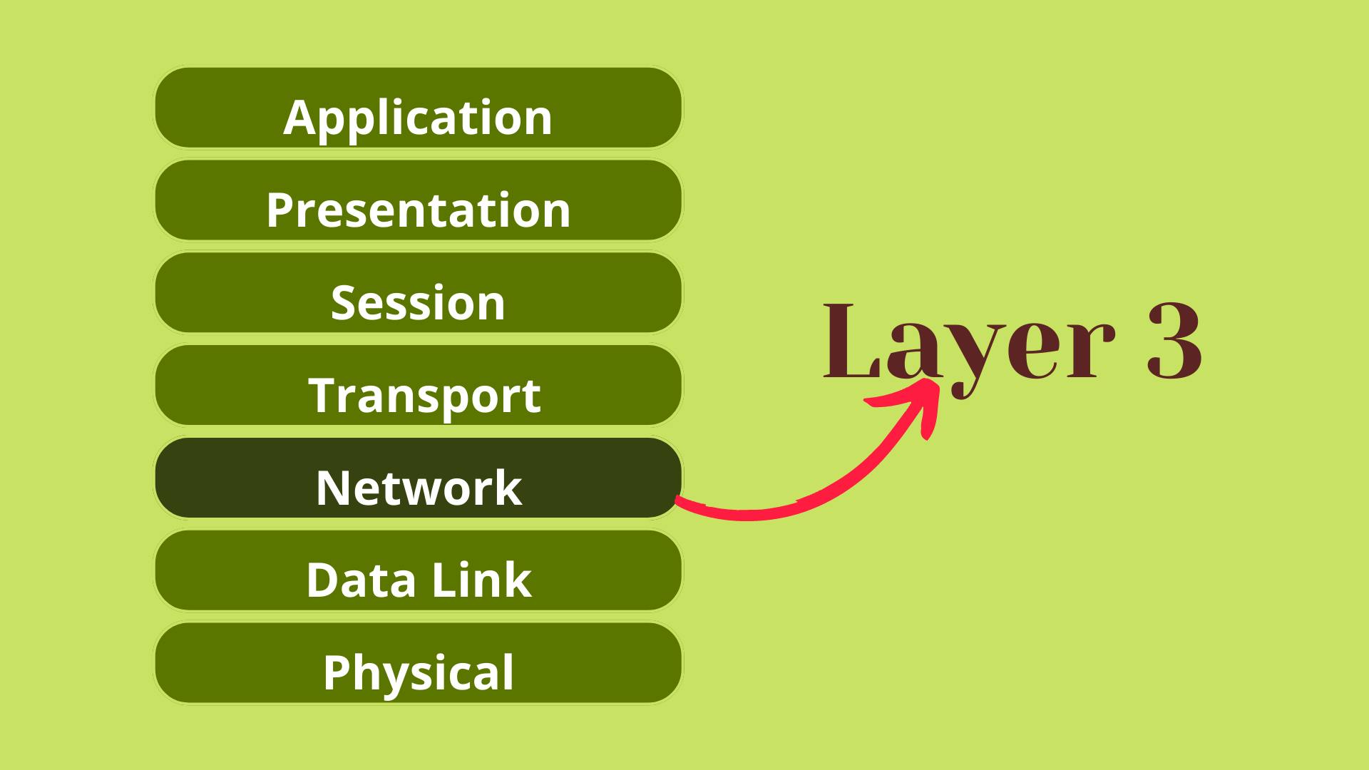
Layer 3 You have likely heard the term layer 3 switches or layer 2 switches. In our OSI model Layer 3, the Network has a goal of end-to-end delivery, this is where we see our IP addresses.
Routers and hosts exist at layer 3, remember the router is able to route between multiple networks. Anything with an IP could be considered Layer 3.
So why do we need addressing schemes on both Layers 2 and 3? (MAC Addresses vs IP Addresses)
If we think about getting data from one host to another, each host has an IP address but there are several switches and routers in between. Each of the devices has that layer 2 MAC address.
The layer 2 MAC address will go from host to switch/router only, it is focused on hops whereas the layer 3 IP addresses will stay with that packet of data until it reaches its end host. (End to End)
IP Addresses - Layer 3 = End-to-End Delivery
MAC Addresses - Layer 2 = Hop to Hop Delivery
Now there is a network protocol that we will get into but not today called ARP(Address Resolution Protocol) which links our Layer3 and Layer2 addresses.
Transport
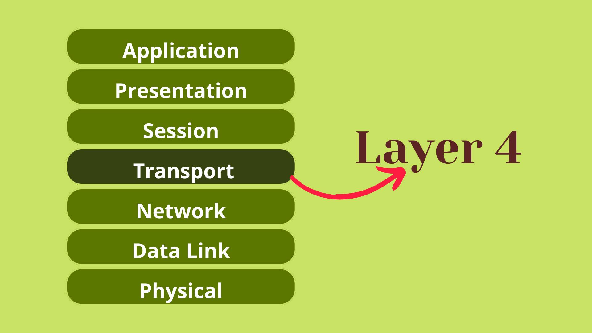
Layer 4 Service to Service delivery, Layer 4 is there to distinguish data streams. In the same way that Layer 3 and Layer 2 both had their addressing schemes, in Layer 4 we have ports.
Addressing Schemes:- Ports (a) 0 - 65535:- TCP (Reliability) (b) 0 - 65535:- UDP (Efficiency)
HTTPS:- TCP/443
HTTP:- TCP/80
IRC:- UDP/6667
Session, Presentation, Application
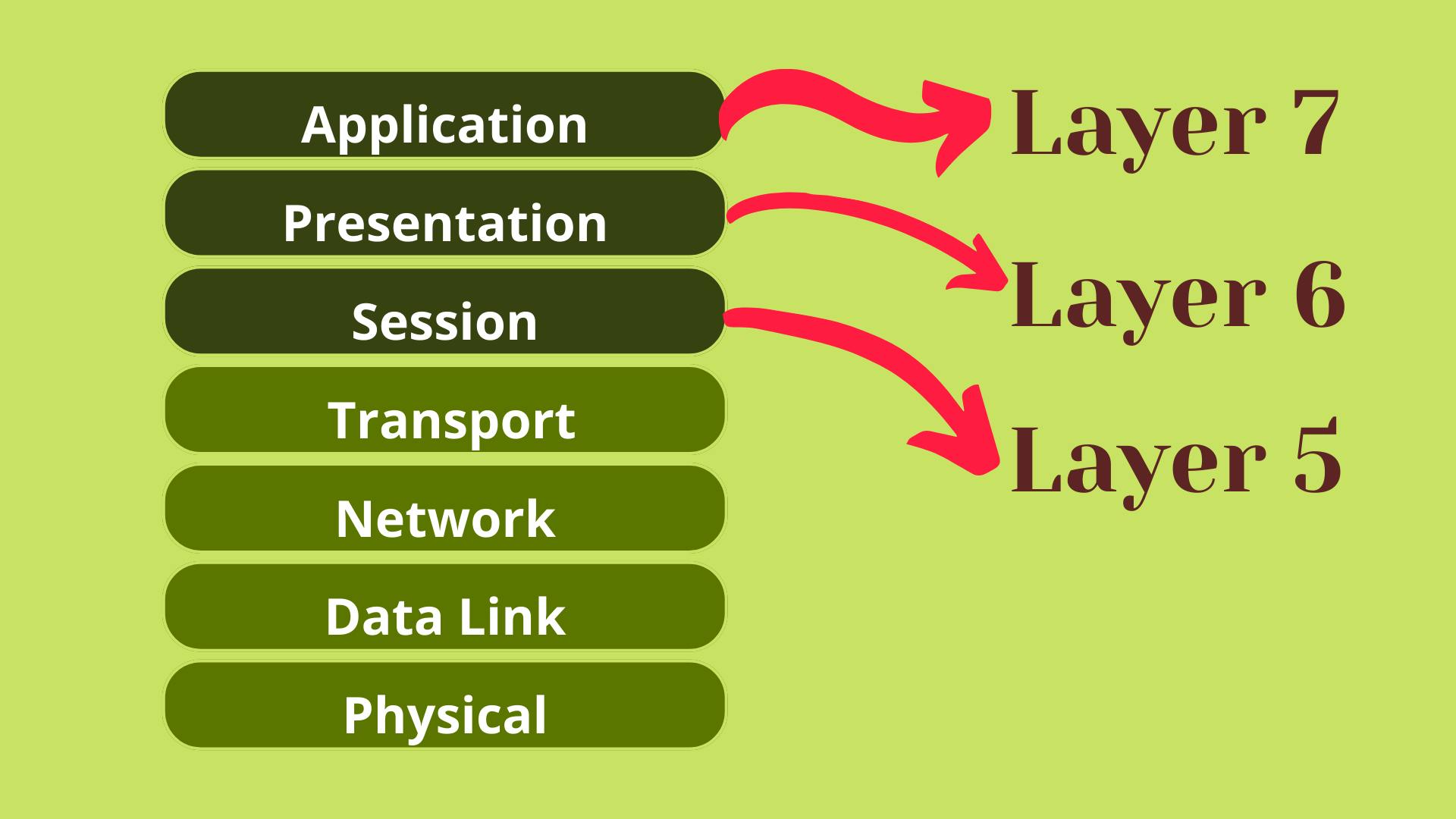
The distinction between Layers 5,6,7 is or has become somewhat vague.
It is worth looking at the TCP IP Model to get a more recent understanding.
Let's now try and explain what's happening when hosts are communicating with each other using this networking stack. This host has an application that will generate data that is meant to be sent to another host.
The source host is going to go through what's known as the encapsulation process. That data will be first sent to layer 4.
Layer 4 is going to add a header to that data which can facilitate the goal of layer 4 which is service-to-service delivery. This is going to be a port using either TCP or UDP. It is also going to include the source port and destination port.
This may also be known as a segment (Data and Port)
This segment is going to be passed down the OSI stack to layer 3, the network layer, and the network layer is going to add another header to this data. This header is going to facilitate the goal of layer 3 which is the end-to-end delivery meaning in this header you will have a source IP address and a destination IP, the header plus data may also be referred to as a packet.
Layer 3 will then take that packet and hand it off to layer 2, layer 2 will once again add another header to that data to accomplish layer 2's goal of hop-to-hop delivery meaning this header will include a source and destination mac address. This is known as a frame when you have the layer 2 header and data.
That frame then gets converted into ones and zeros and sent over the Layer 1 Physical cable or wifi.
So this is all about the OSI model. I will be sharing more about networking.